Building a plant table: (2/3) quick angled bridle joints
Like the previous post, we’re working towards the construction of a plant table. The design I was building attempted to look slim and modern. One aspect of that was thin angled legs. Thin legs aren’t all that stable, on their own, so ideally there is a connection to the table top and then a second connection lower down. Attaching to the top and attaching further down the legs means angled jointery. The intent was to have a linkage come off the legs about 2/3rds of the way down and each linkage would connect to a base. Initially I was planning on a simple angled mortise & tendon joint, however the legs were thin enough that it seemed like a location which could easily crack down the line. Stylistically I could see either a proud tendon in the style of greene and greene or a stopped tendon looking nice, but no need to overcomplicate things.
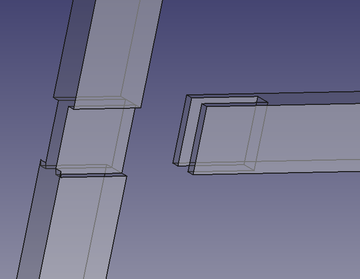
I ended up going with a T bridle joint. As for the angle of the legs, they were all splayed out by an extra 10 degrees. With a 10 degree splay, it looks like:
So, with that goal in mind, what’s a good way to create the joint? The leg has exposed jointery which is easy to mark so that piece is an everyday normal bit of woodworking. The angle within the horizontal linkages though is less trivial to do by hand. In order to ensure the internal face of the linkage mated well with the leg power tools.
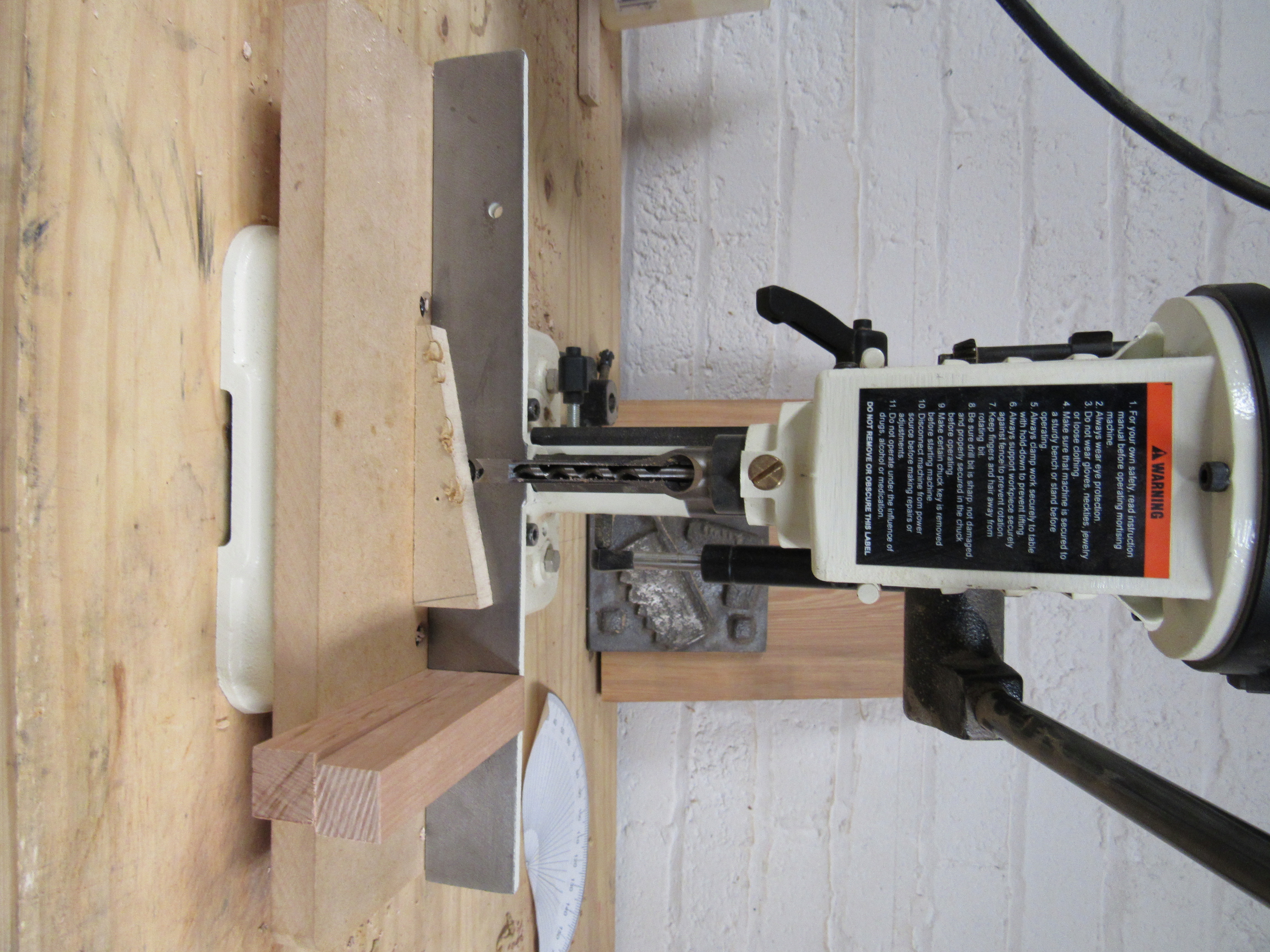
Typically I end up using my mortise machine for cutting holes like that. In this case it was just a matter of using the machine at an angle. The built in fence and clamping wasn’t designed for it, however with a simple wedge and some support blocks we could get going.
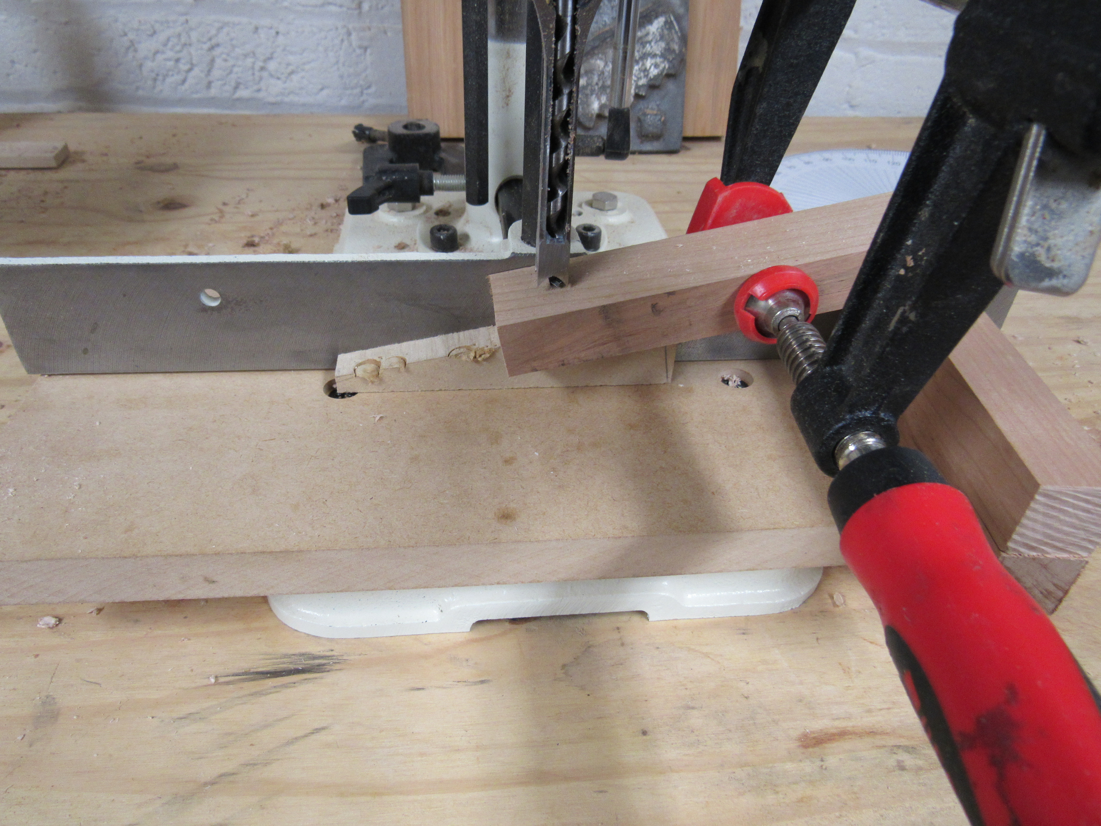
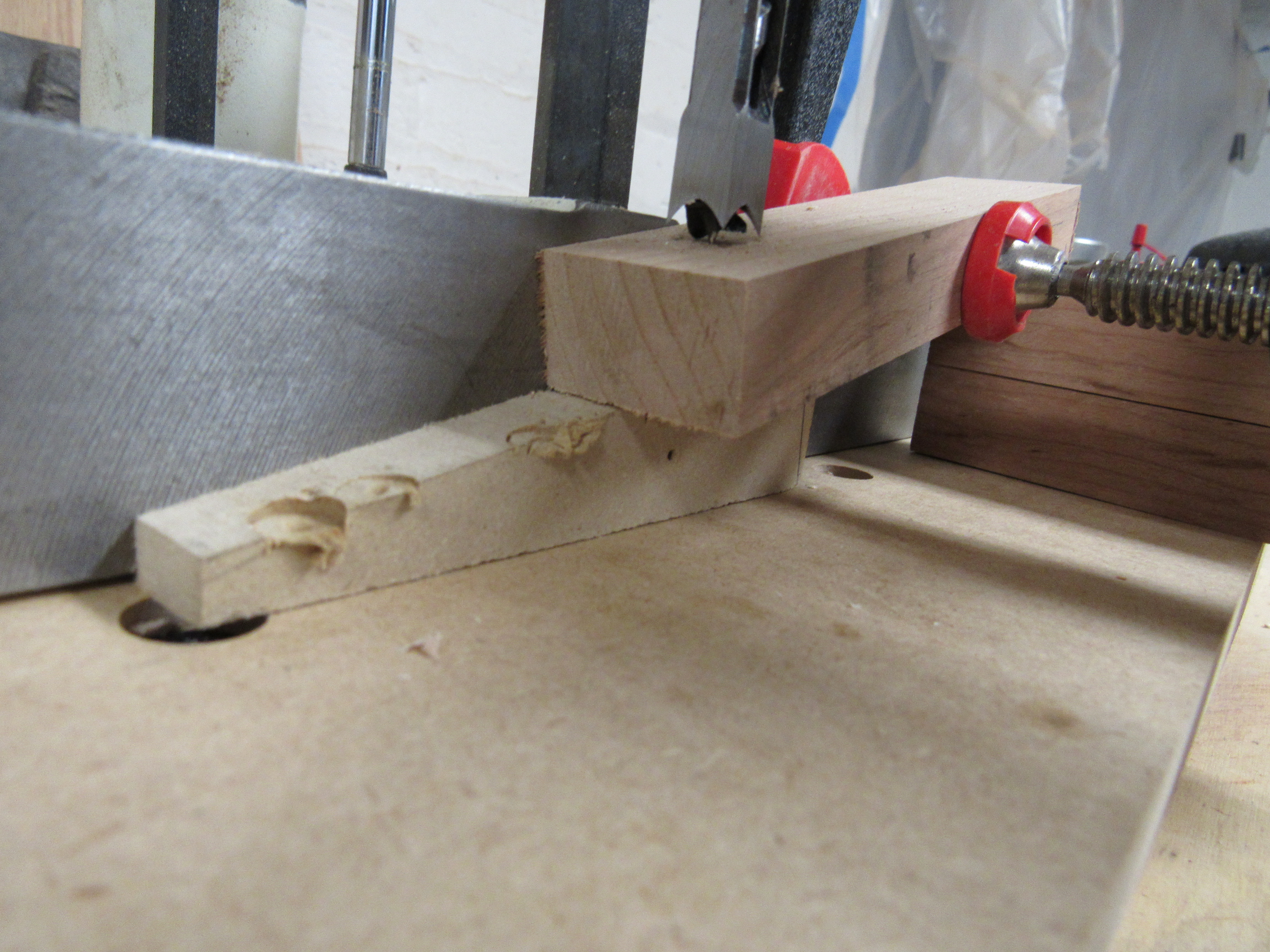
Once we have a piece that we want to turn into a linkage, we can place it on the wedge, use the support blocks to relieve pressure, and attach a single clamp to hold it laterally. By using the mortising machine like this the inside angled edge can be cut cleanly.
After carving the initial hole it’s possible to use the rest of the waste with a bandsaw. As previously mentioned the jointery on the leg can be easily accessed, but it is somewhat unwieldy for my power tools, though a table saw could make quick work of the joint. In my case, some hand saws, a bit of chiseling, and a router plane made fast work. So, what does the result look like? Something like:
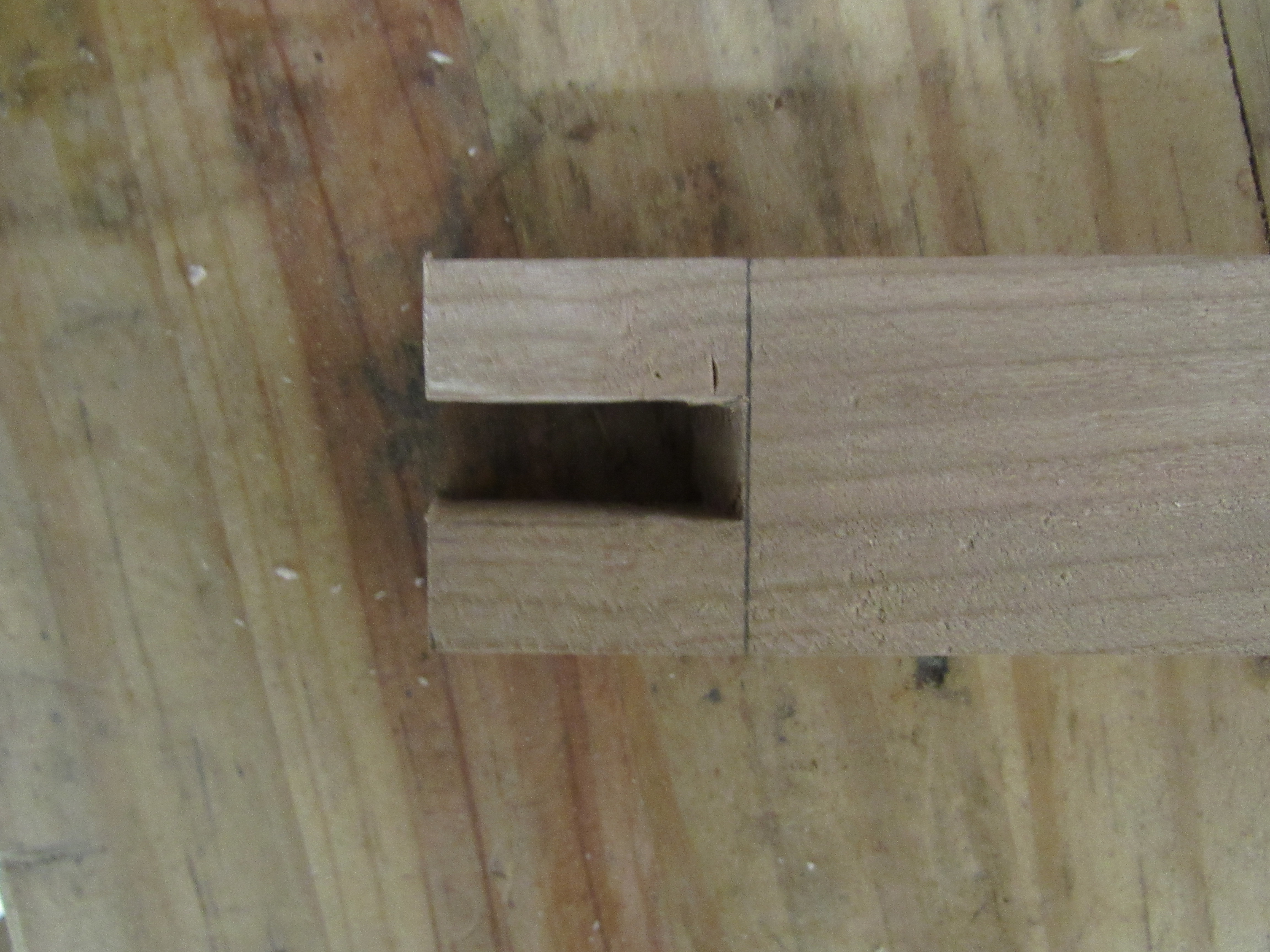
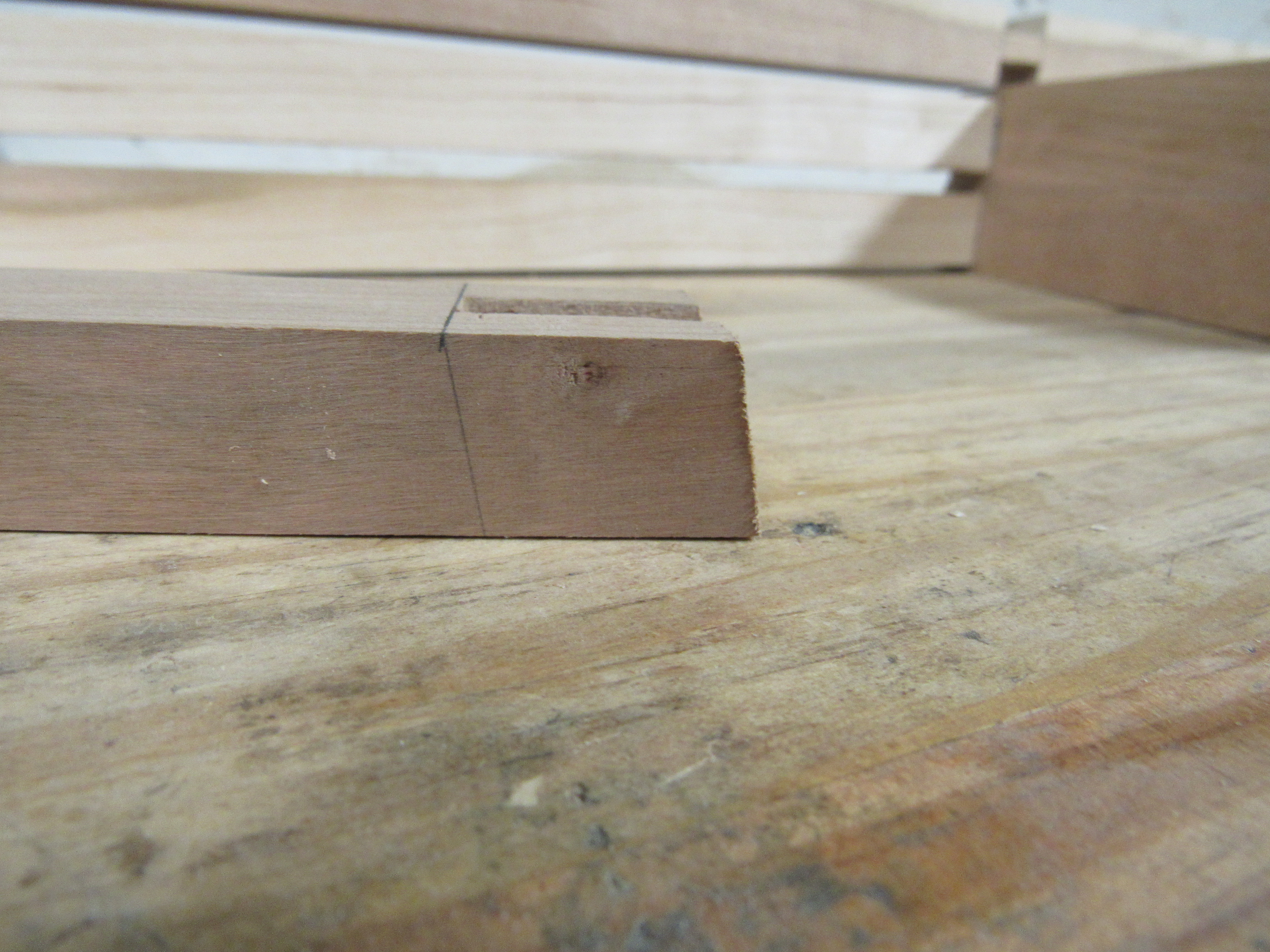
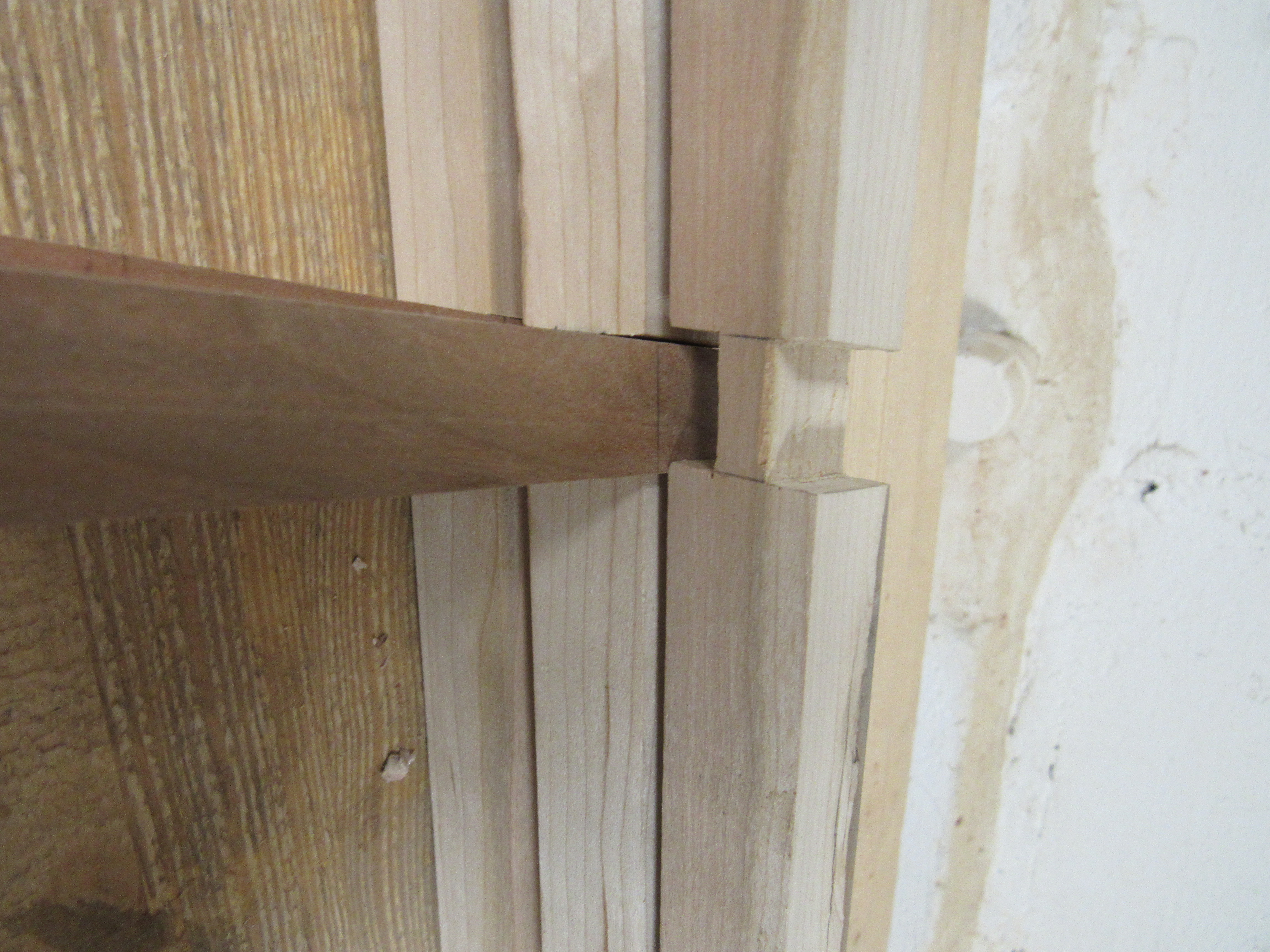
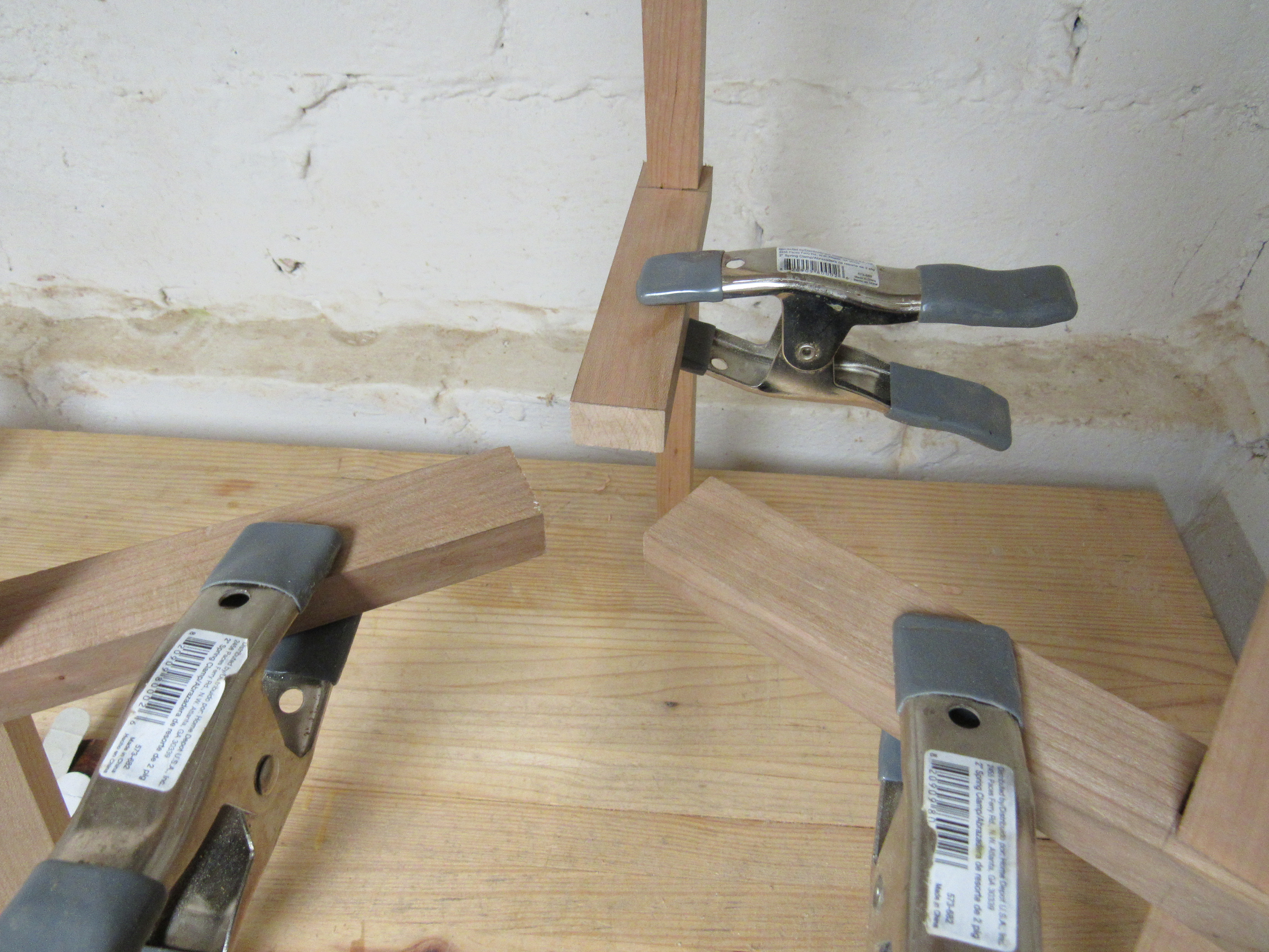
The last picture shows the three legs with the lowers linkages roughly lined up. A cap will connect the lowers, but I’ll leave that detail for the final post in this series.
As per how well does it work, it does a decent job. Since a through mortise is being created there is some occasional blowout. The tearing could be minimized by using a wider sacrificial wedge, but I’ll leave that until next time. While mortise machines aren’t a common shop tool I figured I’d throw this tool tip out there for others or at worst, myself next time I approach a similar task.